Sunday 23 May 2021

Evaluation for astronomical imaging of the Arducam adaptor for the Raspberry Pi HQ Camera. A circuit board to convert the Pi HQ camera into a USB camera.

The Raspberry Pi HQ camera and the Arducam circuit board

The Raspberry Pi High Quality (HQ) camera is a high-resolution camera intended for the Raspberry Pi. It interfaces with the Raspberry Pi SBC via a ribbon cable. Part of the work of the camera is done by the GPU on the SOC.

We have tested the PI HQ camera previously to look at its suitability as an astronomical imaging device.

Firstly, on December 26th 2020, using a Raspberry Pi 4B with a Python capture program I had written. Very promising results were obtained, including some 8-bit, 10s exposures of the Orion nebula, as well as some lunar data. The quality of the images obtained was quite good and they showed very few compression artefacts. The blog article can be read at

https://x-bit-astro-imaging.blogspot.com/2020/12/evaluation-raspberry-pi-high-quality.html

Secondly, experiments were done on January 22nd 2021, to control the Pi HQ camera using AstroDMx Capture for the Raspberry Pi, to capture lunar data. 

https://x-bit-astro-imaging.blogspot.com/2021/01/raspberry-pi-hq-camera-work-in-progress.html

The camera was working normally with the Raspberry Pi where the camera constantly streams data to the GPU. The maximum resolution we were able to use was 1600 x 1200. The lunar data were acceptable, but it was evident that there were some very slight compression artefacts.

The tests on these previous occasions were using the Pi HQ camera in its normal configuration attached via a ribbon cable to the camera port on the Raspberry PI SBC.

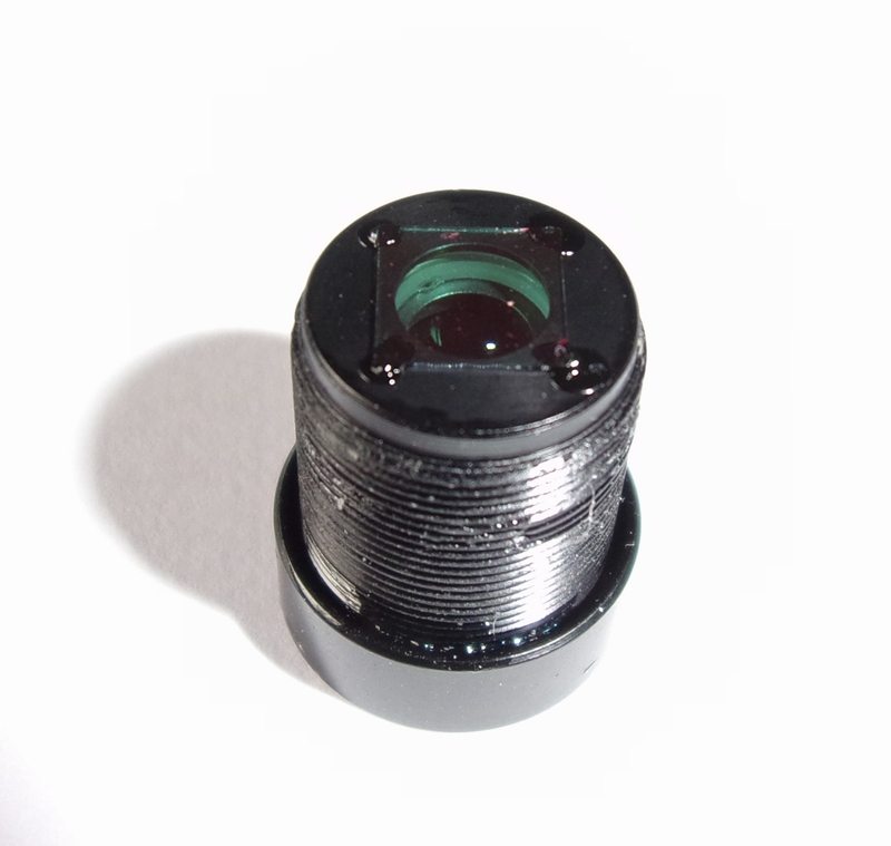
The current test involved the fitting of an Arducam circuit board which connects via a ribbon cable to the Pi HQ camera. Using plastic standoffs, the Arducam adaptor sits as a second layer above the main Pi HQ circuit board.

Click on an image to get a closer view

The Arducam board mounted on the back of the pi HQ camera board


The 1m USB lead connects to the Arducam board by a 4 wire connector. 

It is a shame that such a short cable and such an inflexible cable was supplied with the the Arducam board.

The specifications of the Arducam board are dissapointing, and suggest that little thought has gone into the purpose of the Raspberry Pi SBC or the Pi HQ camera.

The Raspberry Pi SBC is intended as a device for innovation, learning and application in many fields. The take-up of the device in areas other than education is testimony to its versatility.

The Raspberry Pi HQ camera is supposed to be exactly that! A High Quality camera, not just a high resolution camera! The purpose of the Arducam bord is to convert the Pi HQ camera into a USB device that can be used with computers other than the Raspberry Pi; and it does this, but at a cost!

The Arducam board allows a variety of resolutions to be used over USB 2.0 including the highest resolution of 4032 x 3040 down to 640 x 480.

It is noteworthy that for the highest four resolutions, the specifications quote the frame-rates that can be acheived:

4032 x 3040 10fps

3840 x 2160 20fps

2592 x 1440 30fps

1920 x 1080 60fps

The latter resolution is Full HD 1080p

This, in combination with the fact that the Arduboard only offers Motion JPEG video compression shows that the priority for the manufacturer was to provide fast frame-rates (regardless of the quality of the frames being streamed).

In fact, what has been done is to convert the Pi HQ camera into a webcam (but what an expensive webcam). No consideration has been taken for the variety of applications that the camera could potentially be used for. No consideration for the fact that some applications require high quality images and possibly long exposures, or even 12 bit output and not necessarily high frame-rates!

Testing the Arducam board plus the Pi HQ camera as a lunar imaging device.

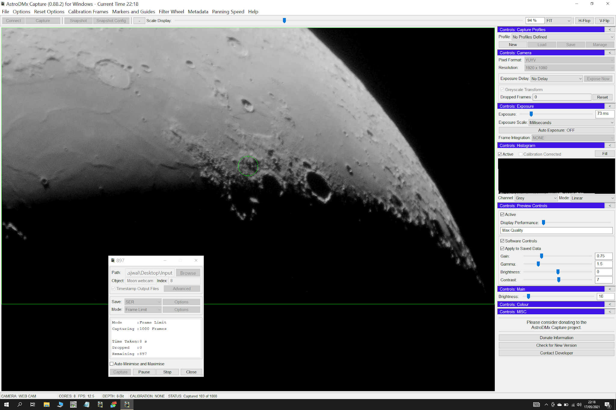
The Arducam/Pi HQ camera was fitted with a Mogg adaptor and placed at the focus of a Bresser Messier-AR-102-xs/460 ED, f/4.5 refractor, on a Celestron AVX mount. AstroDMx Capture for Windows was used to capture a 1000 frame SER file of the 82.1% waxing, gibbous Moon at the maximum resolution of 4032 x 3040.

The Arducam/Pi HQ camera mounted on the scope


Screenshot of AstroDMx Capture for Windows capturing the lunar SER file

The camera offers lots of controls including gain, exposure, gamma, contrast and a number of others. At this stage things look reasonable.

The best 75% of the frames in the SER file were stacked in Autostakkert!, wavelet processed in Registax 6 and post processed in the Gimp 2.10.

Final image of the lunar disk


The final image still looks reasonable, but the devil is, as always, in the detail!

When viewed at full resolution, the image can be seen to be highly compressed! Virtually all of the fine detail on the lunar surface has disappeared in the JPEG compression. The result is a very unnatural looking lunar image devoid of the subtle finer details.

The highly compressed image

There is lots of fine detail in this image that is obliterated by the high compression in the PiHQ/Arducam image.

This image can be compared with an image of the Clavius region of the Moon taken with an SV305,  a camera that does not compress the video stream.

As it stands, the Arducam board does not convert the Pi HQ camera into a USB camera that is of any value for astronomical imaging. When used alone with the Raspberry Pi SBC as it is intended to be used, the Pi HQ camera is a promising astronomical imaging device.

What would be required for the Arducam board to be useful with the Pi HQ camera as an astronomical imaging device?

  • Uncompressed YUYV, whatever the effects on frame-rate.
  • Availablility of RAW, undebayered data.
  • Region of Interest resolutions.
  • Long exposures.
  • 12-bit data output.

Until such time as these things become a reality, it will be necessary to confine the use of the Pi HQ camera to operation with the Raspberry Pi computer in the way that it was designed, and to attempt to extract data from the camera in as high a quality as possible. Sadly, documentation on using the camera is scant and it will be up to individuals to explore the camera as an astronomical imaging device.

If the application was different, for example some sort of surveillance or wildlife observation camera, where a large moving image is required, then the Arducam in conjunction with the Pi HQ camera would provide a solution.


Tuesday 18 May 2021

Can a fully automatic cheap, modern webcam be suitable for an introduction to lunar imaging?

Firstly, to make it clear, this article is not an endorsement or a recommendation for a particular webcam. It is simply reporting the results of an experiment.

The webcam that was used cost less than £14 on Amazon. It is fully automatic in that it offers no functional controls to imaging software. AstroDMx Capture for Windows was used to capture data from the camera. AstroDMx Capture does have software controls that can be applied to save data if required, and this can be helpful if a camera doesn't present any controls.

The webcam used for this experiment.


The webcam was originally purchased to monitor an aquarium in which fish were breeding. It had to be high resolution, and this one is a true Full HD camera. It also had to be able to be focused rather than have an automatic focus.

The camera was easy to disassemble. The front of the camera just pops off, being held in place by small, integral plastic clips. The lens is a Standard S-mount M12 lens of the type often used with board cameras. It had been pre-focused at the factory and then a dab of glue had been used to cement the focus. With a pair of plyers, the glue could be broken and the lens either removed, or focused to a different distance as was required for monitoring the equipment.

Superfluous parts of the camera were removed and discarded and for aquarium monitoring, the camera was held in position with a clamp stand. For the astronomical imaging experiment the lens was removed and replaced by a standard 12mm x 0.5mm Mogg adaptor.

The camera lens


The lens replaced by a Mogg adaptor
The lens has a UV/IR cut filter attached to the bottom of it, so the filter is removed along with the lens

It is therefore necessary to fit a UV/IR cut filter to the front of the Mogg adaptor. This corrects the colour balance, which would otherwise have a pink shade, but also eliminates the UV and IR wavelengths that may not come exactly to the same focus as the visible light in a telescope that uses lenses.

The front of the camera housing could easily have been clipped back in place, but it was left off to provide ventilation and heat dissipation from the electronic components. In addition, two superfluous LEDs were cut away from the circuit board. They serve no function for the camera and produce unwanted light. It is standard practice to remove any microphone from webcams as sound is not required.

It was discovered that the camera shows no pixel vignetting a phenomenon that is a blight to many modern webcams when they are adapted for astronomical imaging. Cameras which have proper lenses and M12 threads such as the camera tested here are the least likely to show pixel vignetting. On the other hand, cameras with very small sensors, lens threads smaller than M12 and tiny lenses, that are often little more than pinholes, often show pixel vignetting. The lack of pixel vignetting is a bonus for this camera.

Legacy webcams and some modern webcams have controls that are available to imaging software, and are desirable for optimising the properties of the video stream such as brightness, contrast and maybe even exposure. This camera offers no functional controls to imaging software. The camera is intended to be a high resolution video conferencing webcam that will automatically adapt to different lighting conditions in order to maintain an optimal image. Moreover, in order to maintain a satisfactory frame-rate at high resolutions, compression of the video stream is automatic.

It was the purpose of this experiment to determine whether the automatic features of the camera would be able satisfactorily to cope with the lighting on the Moon as 'seen' by the camera through the telescope; and secondly, to determine whether the compression of the video stream would result in compression artefacts that would ruin the final stacked image. If the camera performed well enough in both of these aspects, then it might be possible to conclude that such a camera might be suitable for outreach work and possibly as an introduction camera to lunar imaging.

The webcam was placed at the Cassegrain focus of a Skymax 127 Maksutov that was mounted on a Celestron AVX mount. AstroDMx Capture for windows was used to stream video of the 30.5% waxing Moon, and to capture 1000-frame SER files at maximum resolution of 1920 x 1080. The software was set to map to greyscale which would produce a greyscale file of only 1/3 the filesize of a colour image. The camera was oriented to capture the maximum amount of the Moon and the terminator was the area of interest.

Click on an image to get a closer view

Screenshot of AstroDMx Capture for Windows capturing a SER file of part of the lunar terminator

The best 50% of frames in the SER file were stacked and wavelet processed in Registax 6 (which is able to stack monochrome SER files, Autostakkert! can stack colour SER files). The resulting image was reoriented to the correct orientation.
The post-processed image

Screenshot of AstroDMx Capture for Windows capturing a SER file

The post-processed image

Screenshot of AstroDMx Capture for Windows capturing a SER file

The post-processed image

Screenshot of AstroDMx Capture for Windows capturing a SER file

The post-processed image

The individual panes were stitched into a mosaic of the terminator using Microsoft ICE

The conclusion is that the automatic functions of the webcam coped quite well with the lighting conditions on the Moon and it may be that a cheap, fully automatic camera such as this one could be suitable for outreach and/or as an introduction to lunar imaging.


Thursday 13 May 2021

Setting up AstroDMx Capture for Windows and Deep Sky Stacker Live (DSSL) to work with each other.

The object of this exercise is to live stack images being captured by AstroDMx Capture for Windows.

The procedure is simple, but it will help to have it shown step by step.

Click on an image to get a closer view

Preparing the ground

This needs to be done on the same date that the imaging is going to be done.

First of all, set up two folders on the desktop (They could be anywhere, but the desktop is convenient). The folders are called Input and Stack Output (You can call them what you want, but meaningful names help).

Launch AstroDMx Capture for Windows.

Then click on Options and Setup Output format.


Change the  Save Folder to Input on the desktop


To set up everything properly we need AstroDMx Capture to save just one file into the Input folder. We have called this file (Object Name) First. The file index will be set to 1. Make sure that the Save Image Sets into Separate Directories remains UNCHECKED Click on OK.

Then click on Capture. The Capture dialogue is invoked. You will see that the Object is called First. Set the Frame Limit to 1.


In the Capture dialogue that has just been set up, click on the Capture button.


This will create a sub-folder labelled with today’s date in the Input folder on the desktop. Within that folder, the captured file will be placed. Because the Save Image Sets into Separate Directories box was unchecked, an information box will appear to remind you of this. Just click on OK in the information box.


The single image called First will be saved in the date-stamped folder within the Input folder on the desktop, and a message will appear saying the the capture is Complete.


If you open the Input folder, you will see that it now contains the date-stamped folder in which the image has been saved. This folder is the one that DSSL will monitor for new files appearing so that it can stack them.


Open this date-stamped folder and delete the files that have been saved there.


The date-stamped folder will then be empty and ready to receive captured images of an astronomical object.


Doing the Live Stacking

When imaging is shortly to begin, launch DSSL and click on the Settings tab.

Click on <Click Here to select the output folder> and navigate to the Stack Output folder on the desktop. Click on OK.


Then Click on Apply Changes.


At the very top  of the DSSL application window, to the right of Monitoring, Click on <Click here to select the Monitored Folder>.

Then navigate to the Input folder on the desktop and the date-stamped folder within it. This is the folder into which AstroDMx Capture will deposit the captured images.

It will be noted that in the settings box, the default is not to start stacking until 5 images are in the monitored folder. This so that when 5 images are available, DSSL will be able to select the best to use as a reference.


When capturing has begun, you can open the date-stamped folder within the Input folder and watch the images arrive. As soon as the first image arrives in the folder, click on the triangular Monitor button in DSSL. As soon as 5 images have arrived in the folder, Click on the circular Stack button in DSSL and the live stacking will begin.

You can then click on the Stacked Image tab and the image will be displayed. You will need to stretch the image using the controls at the top-right of the Stacked Image window until you are satisfied with the appearance of the stacked image. It should be noted that this does not affect the stacked image data and is to optimise the image for viewing only.

When all of the images have been captured then the Stacked image can be saved to file.

DSSL is intended for use in the field to watch the progression of the stacking of captured images. It uses the same stacking engine as DSS but does not have the facility to dark-frame or flat-field correct the images before stacking. All it does is to cosmetically  remove hot pixels.

However, when used in conjunction with AstroDMx Capture for Windows as shown here, advantage can be taken of AstroDMx Capture’s ability to do live dark-frame and/or flat-field correction.

This means that the resulting stacked image can be dark-frame calibrated during the capture process, so it is suitable for further processing.

Live dark-frame and flat field calibration with FITS images will soon be implemented in AstroDMx Capture.

Screenshot of an actual imaging session.


In this case, DSSL was in dark mode. Dark mode is useful for imaging but for this article it was turned off so that the writing would be easier to read.

Just beneath the Stacked Image tab can be seen Click here to save the stacked image to file. If this is clicked then the stacked image can be saved to file.

At the top-right of the DSSL Stacked Image window are the sliders for stretching the Live-Stacked image for optimal viewing.


Friday 7 May 2021

Live deep sky image stacking with AstroDMx Capture for Windows and Deep-Sky Stacker Live

Deep Sky Stacker Live (DSSL) is a separate module that installs automatically with Deep Sky Stacker (DSS).

DSSL is intended for use in the field to watch the progression of the stacking of captured images. It uses the same stacking engine as DSS but does not have the facility to dark-frame or flat-field correct the images before stacking. All it does is to cosmetically  remove hot pixels. The DSSL manual states that ‘Deep Sky Stacker Live does not have all the features that are needed to create images that can be post-processed accurately’. DSSL is also only able to use the average stacking method as it works with an unknown total number of images (because they are stacked as they are captured). This is a limitation that has to be accepted if live stacking is to be performed. So DSSL is intended for use in situations such as outreach and to satisfy the imager that an acceptable image stack will be producible from the data when they have been collected, as well as producing pleasing on-screen images during the capture process.

AstroDMx Capture is able to capture and save dark-frames as well as a master dark-frame and also capture and save flat-fields and a master flat-field. These master-darks and master-flats can be applied in real-time during the capture process. This means that using DSSL in conjunction with AstroDMx Capture for Windows, the major limitations to producing an image stack suitable for a final post-processing are largely removed.

This imaging session was an experiment to test the use of AstroDMx Capture for Windows in conjunction with DSSL, along with pulse auto-guiding, to produce a pleasing on-screen display of the stacked image as it is added to, and then to post-process the final stacked image to produce a final result.

Equipment used

Windows 10 laptop running AstroDMx Capture for Windows for imaging and DSSL

Fedora Linux laptop running PHD2, multi-star pulse auto-guiding

Celestron AVX GOTO mount.

SVBONY SV165 Guide-scope D=30mm F=120mm.

SVBONY SV305 camera for pulse auto-guiding.

Bresser Messier-AR-102-xs/460 ED, f/4.5 refractor modified for motor focus. 

ZWO ASI178MC CMOS OSC, USB3.0, 14-bit imaging camera.

JJC DHS-1 USB Lens Heater Strip Dew Remover on the imaging scope and the guide scope.

AstroDMx Capture for Windows was used to capture 30 x 1 minute exposures of M3 and 30 x 1 minute exposures of M5, real-time corrected with an AstroDMx Capture generated master dark-frame. DSSL running alongside AstroDMx Capture for Windows was used to monitor the folder into which AstroDMx Capture was saving the images, and to live-stack them as they were captured.

AstroDMx Capture for Windows was set up to save data to a folder that had been created earlier.

DSSL was set to monitor this folder and to start stacking after 5 images had been captured. (This allows DSSL to determine the best quality image to use as the reference frame for the stacking, before the stacking starts)

Click on an image to get a closer view

Screenshot of guiding whilst gathering the data on M3


Screenshot of AstroDMx Capture capturing the M3 data and DSSL stacking the captured data and showing the stacked image.


The data were post processed in the Gimp 2.10 and Topaz AI sharpener (which also reduced noise)  to produce the final image.

M3 Globular cluster


Screenshot of pulse auto-guiding whilst gathering the data on M5, the Rose cluster.


Screenshot of AstroDMx Capture capturing the M5 data and DSSL stacking the captured data and showing the stacked image.


The data were post processed in the Gimp 2.10 and Topaz AI sharpener to produce the final image.

M5 The Rose globular cluster


The experiment was a success and demonstrates that it is possible to use DSSL in conjunction with AstroDMx Capture for Windows to produce pleasing images of the stacked image, and to save it in a form that is suitable for post-processing.