Sunday 28 June 2020

Diffraction spikes attractive and sometimes useful

While we were testing a USB tethered Canon EOS 4000D DSLR with AstroDMx Capture for Linux using an f/5, 6" Celestron Omni XLT 150, my attention was drawn to the diffraction spikes on the brighter stars in the final images.

Screenshot of AstroDMx Capture for Linux capturing data on the Trifid nebula

The Trifid nebula showing diffraction spikes on the brighter stars

The Swan nebula showing diffraction spikes on the brighter stars

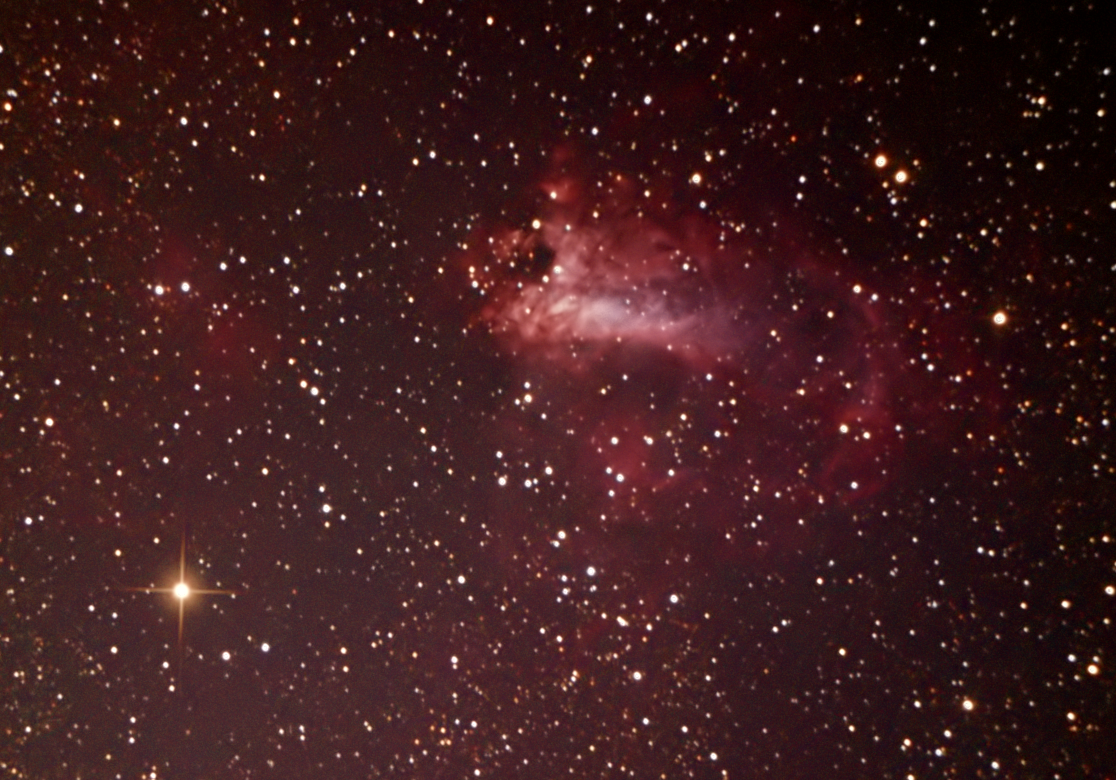
Many people find these diffraction spikes attractive. Some software has functions to add artificial diffraction spikes to images from refractors, and some even place cross wires across the front of a refractor to create real diffraction spikes.

The diffraction spikes are caused by the spider supports for the secondary mirror in a newtonian reflector.

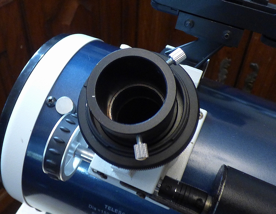
Newtonian reflector showing the spider supporting the flat secondary mirror
 
The diffraction spikes are caused by the fact that light really does bend around the spider vanes, so that interference patterns are created. This bending of light around edges leads to the fact that shadows always have soft edges rather than hard, sharp edges.

The first recorded accurate observations of the diffraction of light and the naming the phenomenon 'diffraction' were due to the Italian Francesco Maria Grimaldi in 1660.

James Gregory FRS discovered diffraction gratings by passing sunlight through a feather and observing that the light was split into the colours of the rainbow and a diffraction pattern was observed. In a letter to the mathematician John Collins in 1673, he invites Collins to inform Isaac Newton of a small experiment that he performed  by allowing sunlight through a small hole into a darkened house, and passing the light through a feather onto white paper. He observed a number of small circles and ovals around a central white point and the rest being 'severally coloured'. Of Newton, he says 'I would gladly hear his thoughts on it.'

He made this observation a year after Isaac Newton had published his work in 1672 on using a prism to split white light into  its component colours.

We did a more modern version of Gregory's experiment, by shining lasers of different coloured light through a feather and observing the diffraction patterns produced. In this animation, it can be seen that the red dots produced by a red laser producing coherent light of 650nm wavelength, were further apart than the green dots produced by a green laser producing coherent light of 532nm wavelength.

Animation of the passing of red and green laser light through a feather.

The feather was examined under a microscope where the cross-axis structure of the barbs and barbules between them could be observed.

AstroDMx Capture connected to a USB electronic microscope

High power image of the barbs and cross, barbules between them

To make the observation even clearer, the red and green laser light was passed alternately through 
diffraction gratings; one grating was a one-axis grating and the other was a two axis grating.

Animation of the passing of red and green laser light through a one axis diffraction grating.

Animation of passing red and green light through a two axis diffraction grating.

In each of these animations it can be seen that the dots of the red diffraction interference pattern are further apart than the dots of the green diffraction interference pattern. This is because longer wavelengths are diffracted through greater angles than shorter wavelengths.

To demonstrate this further a, blue laser producing coherent light of 405nm was introduced and the diffraction patterns produced by all three lasers, with otherwise identical optical geometries, at the same scale, were combined into a single image.

Combination of images of diffraction patterns produced by red, green and blue light

Shining light from a white LED through the two diffraction gratings produced spectra showing that long wavelengths are diffracted more than short wavelengths.

Single axis diffraction grating
In this example, the source of white light is to the right of the grating and low down

Two axis diffraction grating
In this example, the source of light is behind the grating. 

In contrast to a diffraction grating, a prism refracts short wavelengths more than long wavelengths. This experiment was done with a prism in a darkened room with sunlight allowed through a slit onto a prism that was standing on a sheet of white paper. The light was coming from the right.
It can be seen that the shorter wavelength blue light was refracted through a greater angle than the angles through which the longer wavelengths green, yellow and red light were refracted. This phenomenon is responsible for the atmospheric dispersion seen when imaging planets low in the sky. The atmosphere acts as a prism and refracts the short wavelengths higher away from the sun.

This is an image of Venus captured with a ZWO ASI178MC camera using a region of interest and a Skymax 127 Maksutov mounted on a Celestron AVX mount. A 10,000 frame SER file was captured by AstroDMx Capture and the best 10% of the frames were registered and stacked in Autostakkert!
The Sun was below the horizon on the bottom right.

Animation of the Stacked images with and without RGB channels registration.
It can be seen that the blue light was refracted further away from the direction of the Sun than was the red light, creating the atmospheric dispersion effect.


In 1663 Gregory wrote a book entitled Optica Promota (The Advance of Optics) which was about lenses and mirrors, but contained a description of the first reflecting telescope that used a parabolic mirror. This was five years before Isaac Newton produced his first functional reflecting telescope in 1668. It is possible that Newton had read Optica Promota, so he could have been influenced by Gregory. James Gregory didn't have the skills to build the telescope for himself and had difficulty trying to find an optician with the necessary skills to build one for him. It was eventually built by Robert Hook ten years later. 

The Gregorian telescope had a Cassegrain configuration with folded optics so that the image was brought out through a hole in the centre of the primary mirror to what has become known as the Cassegrain focus after the design of a reflecting telescope published in 1672 in Journal des sçavans, the first academic journal to be published in Europe. Other people were also working on reflecting telescopes at this time. In fact, the idea was not new as Galileo Galilei and others had previously discussed the use of a mirror as the objective.

The Swansea Astronomical Society owns a Gregorian telescope shown here
Gregorian reflector

Gregorian reflector

In 1668, the same year that Newton produced his reflecting telescope, Gregory was elected to the Royal Society. Newton was elected to a Fellowship of the Royal Society four years later in 1672.

Using diffraction spikes to achieve perfect focus using a Bahtinov Mask

The Bahtinov mask was invented in 2005 by the Russian astrophotographer Pavel Bahtinov as an aid to the precise focusing of telescopes by making use of diffraction spikes. The Mask is placed at the front of the telescope, It has three sets of slots at angles as shown in the image. When pointed at a bright star, 3 diffraction spikes are produced  that move in relation to  each other as the scope moves through focus. When the star is in perfect focus, the central diffraction spike is exactly central in relation to the other two spikes. When it is out of focus, the central spike is on one side of centre or the other side, depending on whether the star is inside or outside focus.

Bahtinov Masks

Bahtinov Mask on the front of a telescope

A ZWO ASI178MC camera was placed at the Newtonian focus of a 6", f/5 Newtonian, with a Bahtinov mask fitted to the front. The scope was aligned on Altair.
AstroDMx Capture for Linux was used to capture snapshots of the diffraction spikes, either side of focus and at perfect focus. An animation was produced.

Diffraction spikes produced by a Bahtinov mask at perfect focus and either side of focus

Focus is adjusted until the central spike is exactly central between the other two spikes as shown above. When the scope is either side of focus, the central spike is not central with respect to the other two spikes.

AstroDMx Capture for Windows, macOS or Linux (Including Raspberry Pi) can be downloaded freely here:

Wednesday 17 June 2020

Preparing a 6” Newtonian for versatile imaging

Preventing the primary mirror from misting up in cold weather 
and the prevention of the ingress of light at the base of the scope.

The telescope used here is a Celestron Omni XLT 150 f/5 Newtonian.

click on an image to get a closer view.

Whilst the mirror is at the bottom of a long tube, the bottom of the mirror is very close to the outside environment and it is likely that it can cool rapidly from the bottom outside. Protecting the mirror from losing excessive heat from the back of the mirror can be addressed in a number of ways. I have written about this previously HERE, but I shall revisit the issue here, as well as other things that prepare the telescope for astronomical imaging. The first stages are illustrated using a Skywatcher Explorer 130 PDS 130mm, f/5 Newtonian from a previous blog.

A rubberised cover is often at the back of the primary mirror by the manufacturer.
Illustrated by a Skywatcher Explorer 130 PDS 130mm, f/5 Newtonian

A disk of polystyrene is cut and fitted over the black layer
Illustrated by a Skywatcher Explorer 130 PDS 130mm, f/5 Newtonian

Then a disk of thin black styrene board is placed on top of the polystyrene disk
Using the Celestron Omni XLT 150
This has been done here with the Celestron Omni XLT 150

Finally, to prevent any light from getting around the disks of polystyrene and styrene board, a further disk of black styrene board is placed up to the edge of the base. Despite the presence of the black, rubberised sheet often placed on the back of the mirror by the manufacturer, light can sometimes leak into the back of the scope, particularly if light from a street light falls on the bottom of the scope.

Celestron Omni XLT 150

Diagram of the insulating and light-excluding components

Fitting of DSLR and eyepiece adaptors

Attaching and correctly aligning a DSLR direct camera attachment directly to the focuser and optionally modifying the focuser to hold a filter, such as a light-pollution filter in front of the DSLR. It is worthwhile spending the time slackening off the three grub screws and turning the DSLR connector so that the camera will be aligned the desired way when attached. Once the camera alignment is satisfactory, the grub screws can be tightened.

I have written about this previously HERE in more detail.

DSLR connector screwed in place

Light-pollution or other filter screwed in place


Eyepiece adaptor screwed on after the filter

Eyepiece holder without a filter 

Fitting a motor focuser to the scope.

A motor focuser prevents the scope from being vibrated during focusing, and is particularly important if a dual-speed focuser is not fitted.

Here a standard Skywatcher motor focuser is fitted after removing one of the focusing knobs.


Preventing the Tube from slipping through the rings when the tube is turned in the rings


Four adhesive felt strips were attached to the tube (two on one side of the tube and two on the other side). When the tube has to be turned, for example, when the mount has had to reverse after passing through the meridian. Without the felt strips in place, the tube can slip downwards through the rings and change the balance of the whole system. With the felt strips in place, the tube rotates easily without slipping.

Using the modified Celestron Omni XLT 150, f/5  Newtonian with AstroDMx Capture for Linux to capture the globular cluster M13

A ZWO ASI178MC camera was placed at the Newtonian focus of a Celestron Omni XLT 150, f/5 Newtonian mounted on a Celestron AVX EQ, GOTO mount.

AstroDMx Capture for Linux was used to capture 40 x 30s exposures of M13 with matching dark-frames.

Screenshot of AstroDMx Capture for Linux capturing data on M13

The best 38 frames were dark-frame corrected and stacked in Deep Sky Stacker, and post-processed in The Gimp 2.10 and Neat Image.

M13

AstroDMx Capture for Windows, macOS or Linux (Including Raspberry Pi) can be downloaded freely here:

Tuesday 9 June 2020

M3 with AstroDMx Capture for Linux, a USB-tethered Canon EOS 4000D DSLR and a Skymax 127 Maksutov.

A Skymax 127 Maksutov was mounted on a Celestron AVX GOTO mount. A Canon EOS 4000D DSLR was placed at the Cassegrain focus and was USB-tethered to a laptop running Fedora Linux and AstroDMx Capture for Linux. AstroDMx Capture controls the DSLR just like any other astronomy camera. Every setting of the camera can be set from the software, which then captures the specified number of images with the specified ISO and exposure values, and stores them on the computer, not on a camera SD card. 

45s exposures were captured of M13 with matching dark-frames. 

Screenshot of AstroDMx Capture for Linux capturing exposures from the USB tethered DSLR
 

The best 23 images were stacked and dark-frame corrected in Deep Sky Stacker. 

The resulting image was post-processed in The Gimp 2.10, Affinity Photo and Neat image. 

M3 


Closer view

Monday 1 June 2020

Further exploration of astronomical snapshots

These posts must not be interpreted as being recommendations for the routine capture of astronomical snapshots, for there is no doubt that the stacking of numerous replicate images increases the signal to noise of the final image, which allows much more sharpening and revealing of detail made possible by wavelet processing. That is the correct way to produce astronomical images.

However, it is a fact that a number of astronomers capture single astronomical images routinely with DSLR cameras. In fact, there are social media groups dedicated to the one-shot astronomical image.

If the astronomical camera is being used primarily in an outreach situation, possibly with a mount that is less than perfectly aligned, the object  of the exercise is to stream images to the computer screen to be enjoyed by visitors to the event. Nevertheless, as we have said before, it may be desirable to capture individual snapshots to preserve a record of what was observed on the night. It was for reasons such as this, and for other applications such as microscopy, that the Snapshot facility was implemented by Nicola into AstroDMx Capture.

However, we needed to find out what kind of results might be obtained by taking a long-exposure snapshot in addition to capturing snapshots of the Moon.

The scope we used  was a Skymax 127 with a 0.5 focal reducer, The camera was a QHY 5L-II-M monochrome CMOS camera.

Screenshot of AstroDMx capture for Linux streaming and capturing Lunar data

Snapshot of the mid-section of the Moon

These images were captured when the jet stream was far to the north of the country and so was not contributing to the degrading of the seeing conditions.

Three overlapping snapshots stitched with Microsoft ICE into a 3-pane mosaic


Snapshot of M13

The equipment capturing M13 data.

A single 30s, 16-bit snapshot exposure was made of M13. Also a single 30s dark-frame snapshot was made in 16-bit mode

Dark-frame snapshot

There are a number of hot pixels present in the dark-frame.

Uncorrected 30s snapshot of M13 in 16-bit mode

The hot pixels are also present in the snapshot

The dark-frame correction was made in the Gimp 2.10 by pasting the dark-frame as a new layer onto the M13 snapshot and subtracting it. Then the image was flattened.

30s snapshot of M13 in 16-bit mode, dark-frame corrected

Dark-frame corrected snapshot stretched in the Gimp 2.1

This is quite a presentable image, which can be compared with an image made by stacking 40 x 30s exposures. the coma on the edge stars is due to the use of s cheap focal reducer in this experiment.

Stack of 40 x 30s exposures

More detail could be stretched out of the stack of 40 x 30s exposures, which had 6.32 x the Signal to Noise ratio of the single snapshot.

It could be tempting to conclude that snapshots are adequate to obtain presentable astronomical images. However, this would be an erroneous conclusion. For detailed reasons look at this earlier blog post, as well as comparing the above two images of M13, and considering the animation at the end of this post.

Capturing a high magnification lunar image

Using a Skymax 127 Maksutov and a 2.5x Barlow with a  QHY 5L-II-M monochrome CMOS camera. Using AstroDMx Capture for Linux, several snapshots of the Albategnius region of the 46.6% waxing Moon were taken at moments of good seeing, and the best image was chosen. Also a 1000-frame SER file was captured of the same region. The best 10% (100 frames) of the SER file were stacked in Autostakkert! 3.1, wavelet processed in Registax 6 and post processed in the Gimp 2.10. The snapshot could not be sharpened without increasing the noise in the image.

The equipment capturing Lunar data

Animation showing the difference between the results obtained from a single snapshot and a stack of the best 100 of 1000 frames captured under the same conditions.

There is no doubt at all that the stacked image is far superior to the single snapshot.

Snapshots have their place, but not for the production of high quality astronomical images.